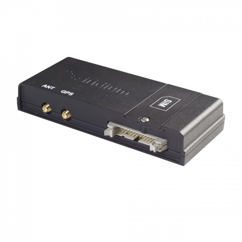
Iridium L-Band Transceiver 9522B Ex Demo - DISCONTINUED (9522B_SCA)

Beam Communications undertakes warranty and out of warranty servicing across our extensive product range.
For further information on our servicing process, warranty items and conditions please click on the button below.
Frequently Asked Questions
Data
This problem occurs when there is poor signal quality. Users who are attempting to make data calls from inside of a building also tend to have this difficulty.
When your call drops, observe the signal strength indicator in the corner of the LCD on the phone or your computer and verify that your signal is in the range of 4 to 5 bars.
If you are not getting 4 to 5 bars of signal, you may want to adjust your antenna location to get a better view of the sky.
If the problem persists, please contact the dealer through whom you purchase service.
To initialise the Iridium data terminal to receive an incoming data call, start a Terminal Program (such as HyperTerminal) with the following settings: 19200* bps, 8, N, 1, Flow Control = None.
Once connected , type the following AT commands:
AT+IPR=x (where x baud of Terminal Program, according to
ATS0=1 (This turns on auto-answer)
1 = 600 bps
2 = 1200 bps
3 = 2400 bps
4 = 4800 bps
5 = 9600 bps
6 = 19200 bps (default)
E.g. AT+IPR=5 sets to 9600bps Terminal rate)
AT&W0 (This stores the current (active) settings to Profile 0 of the RST100).
The device is now ready to answer an incoming data call automatically. During the waiting period, the Data RX activity timeout can expire, and Voice calls can be made (Applies only to RST100 model, with serial numbers > 10001000).
* The baud rate can be set to whatever baud rate the device answering the call is going to need and not necessarily 19.2k. The “RING” string should be decipherable by the target device/program.
Refer to the Beam Data Guide for more information.
Each Iridium sim card comes with two MSISDNs. MSISDN-A is the standard phone number supplied with a sim card for voice and sms. MSISDN-C is the data number.
If the Iridium terminal is configured as a modem to receive and send data, then you will need to dial into the terminal's MSISDN-C number. (This is not an Iridium internet access number).
The sim card/service provider can give you the MSISDN-C.
Also, make sure that the terminal is capable of auto-answering incoming calls if unattended and set to auto baud. Some remote terminals do not respond to auto-baud quite well and therefore it is best to try different baud rates until you can establish a PPP connection.
SBD
The IP Address is 12.47.179.11
directip.sbd.iridium.com / port 10800 which should resolve to 12.47.179.12:10800
Yes, the source IP address that will be utilized to connect to the Iridium gateway needs to be included within the Iridium network firewalls, to allow for successful connection.
This request for DMT access needs to be sent to the partners Iridium Account Manager.
Before an SBD can be sent, the LBT (in the Beam Device) or Iridium satellite phone must be provisioned for SBD. This includes Data being activated on your account and a destination address setup for the SBD to be sent to.
The destination address can be set to a specific IMEI number, an email address, or a direct IP Address / port.
Your service provider will be able to assist you in provisioning of your device.
Refer to the Beam Data Guide for more information on sending SBD's.
Messages sent to an ISU from the Host are sent to the email address: This email address is being protected from spambots. You need JavaScript enabled to view it.
- Placing at least one, and up to a total of four, IMEI(s) into the subject line of the email identifies the destination ISU(s).
- If there is more than one destination IMEIs then list the additional IMEIs on the subject line separated with a single space between each IMEI.
- White listing may be used to restrict the originator of MT-SBD messages to particular IMEIs. This restriction will fork for email and Direct IP.
- The message must contain a properly formatted sender (“From:” address), otherwise the message will be dropped by the GSS.
- The data message to the ISU must be carried as an attachment to the email:
- The attachment name must have a ‘.sbd’ file name extension: E.g. ‘importantdata.sbd’
- File names must be 80 characters or less. (Including the .sbd extension.)
- File names are not case sensitive.
- The maximum size of the binary message (not the Base64 version) is ISU specific and is between one byte and the maximum MT message size stated in Section 1.5
- The GSS will reject message sizes that are too large for a particular ISU type.
- The attachment must use standard Multipurpose Internet Mail Extensions (MIME) Base64 encoding as defined in RFC 2045.
- Multiple messages may be queued by a single email by including the additional separate attachments in the email message, subject to the maximum number of messages permitted in the queue.
- Note that if one of the attachments has an incorrect extension (.sbd), while others are correct then no error indication email will be sent.
- A single email with multiple attachments creates a MT-SBD message from each attachment. In other words – one email with ten attachments creates ten entries for the destination ISU.
- The message body plays no role in the message transfer process; any information contained in the body will be discarded.
- A maximum of 50 messages may be in any ISU’s queue at any one time regardless of whether they where sent as an individual message with attachment or a single message with multiple attachments. The GSS will reject any message over this limit.
Cables/Antennas
The proper torque for the sma connector is between 7 to 10 inch pounds of torque. (81 to 110 N-cm, for those who prefer metric measures).
If this value is exceeded, its possible to break the connector. Please note that if found the antenna connector has been damaged due to over tightening, this will void the warranty.
Inmarsat passive/directional antennas are best suited for fixed installations like buildings, homes, and the likes. The Inmarsat passive/directional antenna is required to permanently point directly to the nearest Inmarsat satellite. It is not suitable for mobile applications.
If you wish to use an Inmarsat satellite setup on a moving vehicle or vessel, consider an active/omnidirectional antenna.
The maximum recommended signal drop from the passive satellite antenna to the Iridium transceiver( either a handset or Beam device) is 3dB. (Not applicable when using RST740).
For optimal performance, we recommend using the shortest length of cable and the fewest number of connectors possible. You must ensure that the cable used conforms to this.
An example of attenuation for RG213 cable is 0.33dB per metre @ 1.6Ghz, therefore the maximum cable length is 8m (allowing up to 0.5dB for cable interconnections).
LMR400 cable in comparison has a better attenuation figure of 0.18dB per metre.
Feel free to use the Beam Iridium Online Cable calculator to design your cable for a Beam Iridium docking station or terminal.
Important: This calculator is best viewed on desktop. Not optimised for mobile viewing.
To use the online Cable Calculator, use the following steps:
- Select the first Cable Type and Enter Length. -> Click Add Cable
- Select the connector on one end of the cable. -> Click Add Connector
- Select the connector on the other end of the cable. -> Click Add Connector
- Repeat for each Additional Cable or connector to get Total Loss in dB.
- Click Clear All to reset Loss calculations.
| Select cable type | Length (metres) | |
| Select connector type | ||
| Allowable Loss: 3dB | Loss dB | |
Iridium L-Band Transceiver 9522B Ex Demo - DISCONTINUED Specifications
Power Input Specifications & Consumption
| Power Average - Voice / Data Call (see note) | 4W |
| Typical current during call (see note) | 800mA |
| Max current during call | 2.5A |
| Input Standby current (average) | 250mA |
| Main Input Voltage - Consumption at +5VDC | 40mV peak to peak |
| Main Input Voltage Range | +4.0V DC to +32V DC |
RF Characteristics
| Multiplexing Method | TDMA / FDMA |
| Input/Output Impedance | 50Ω |
| Oscillator Stability | ± 1.5 ppm |
| Duplexing Method | TDD (Time Domain Duplex) |
| Frequency Range | 1616 MHz to 1626.5 MHz |
| Receiver Spurious Rejection at offsets > 1 MHz (typical) | 60dB |
| Receiver Sensitivity at 50Ω (typical) | -118.5dBm |
| Average Power during a frame (typical) | 0.6W |
| Average power during a transmit slot (max) | 7W |
Environmental
| Temperature | Degrees °C | Degrees °F |
| Operating Temperature Range | -30ºC to +60ºC | -22ºF to +140ºF |
| Storage Temperature Range | -40ºC to +85ºC | -40ºF to +185ºF |
| Operating Humidity Range | 25 to 75% RH | |
| Storage Humidity Range | ≤ 93% RH |
Physical
| Dimensions | mm | inches |
| Width | 81 x 28 x 162 | 3.19 x 1.10 x 6.38 |
| Weight | kg | lbs |
| Transceiver | 0.420 | 0.925 |
Manuals & Guides
Manual 9522B L-Band Transceiver
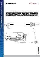
9522B Fly Lead Installation Note
Compliance
Frequently Asked Questions
Data
This problem occurs when there is poor signal quality. Users who are attempting to make data calls from inside of a building also tend to have this difficulty.
When your call drops, observe the signal strength indicator in the corner of the LCD on the phone or your computer and verify that your signal is in the range of 4 to 5 bars.
If you are not getting 4 to 5 bars of signal, you may want to adjust your antenna location to get a better view of the sky.
If the problem persists, please contact the dealer through whom you purchase service.
To initialise the Iridium data terminal to receive an incoming data call, start a Terminal Program (such as HyperTerminal) with the following settings: 19200* bps, 8, N, 1, Flow Control = None.
Once connected , type the following AT commands:
AT+IPR=x (where x baud of Terminal Program, according to
ATS0=1 (This turns on auto-answer)
1 = 600 bps
2 = 1200 bps
3 = 2400 bps
4 = 4800 bps
5 = 9600 bps
6 = 19200 bps (default)
E.g. AT+IPR=5 sets to 9600bps Terminal rate)
AT&W0 (This stores the current (active) settings to Profile 0 of the RST100).
The device is now ready to answer an incoming data call automatically. During the waiting period, the Data RX activity timeout can expire, and Voice calls can be made (Applies only to RST100 model, with serial numbers > 10001000).
* The baud rate can be set to whatever baud rate the device answering the call is going to need and not necessarily 19.2k. The “RING” string should be decipherable by the target device/program.
Refer to the Beam Data Guide for more information.
Each Iridium sim card comes with two MSISDNs. MSISDN-A is the standard phone number supplied with a sim card for voice and sms. MSISDN-C is the data number.
If the Iridium terminal is configured as a modem to receive and send data, then you will need to dial into the terminal's MSISDN-C number. (This is not an Iridium internet access number).
The sim card/service provider can give you the MSISDN-C.
Also, make sure that the terminal is capable of auto-answering incoming calls if unattended and set to auto baud. Some remote terminals do not respond to auto-baud quite well and therefore it is best to try different baud rates until you can establish a PPP connection.
SBD
The IP Address is 12.47.179.11
directip.sbd.iridium.com / port 10800 which should resolve to 12.47.179.12:10800
Yes, the source IP address that will be utilized to connect to the Iridium gateway needs to be included within the Iridium network firewalls, to allow for successful connection.
This request for DMT access needs to be sent to the partners Iridium Account Manager.
Before an SBD can be sent, the LBT (in the Beam Device) or Iridium satellite phone must be provisioned for SBD. This includes Data being activated on your account and a destination address setup for the SBD to be sent to.
The destination address can be set to a specific IMEI number, an email address, or a direct IP Address / port.
Your service provider will be able to assist you in provisioning of your device.
Refer to the Beam Data Guide for more information on sending SBD's.
Messages sent to an ISU from the Host are sent to the email address: This email address is being protected from spambots. You need JavaScript enabled to view it.
- Placing at least one, and up to a total of four, IMEI(s) into the subject line of the email identifies the destination ISU(s).
- If there is more than one destination IMEIs then list the additional IMEIs on the subject line separated with a single space between each IMEI.
- White listing may be used to restrict the originator of MT-SBD messages to particular IMEIs. This restriction will fork for email and Direct IP.
- The message must contain a properly formatted sender (“From:” address), otherwise the message will be dropped by the GSS.
- The data message to the ISU must be carried as an attachment to the email:
- The attachment name must have a ‘.sbd’ file name extension: E.g. ‘importantdata.sbd’
- File names must be 80 characters or less. (Including the .sbd extension.)
- File names are not case sensitive.
- The maximum size of the binary message (not the Base64 version) is ISU specific and is between one byte and the maximum MT message size stated in Section 1.5
- The GSS will reject message sizes that are too large for a particular ISU type.
- The attachment must use standard Multipurpose Internet Mail Extensions (MIME) Base64 encoding as defined in RFC 2045.
- Multiple messages may be queued by a single email by including the additional separate attachments in the email message, subject to the maximum number of messages permitted in the queue.
- Note that if one of the attachments has an incorrect extension (.sbd), while others are correct then no error indication email will be sent.
- A single email with multiple attachments creates a MT-SBD message from each attachment. In other words – one email with ten attachments creates ten entries for the destination ISU.
- The message body plays no role in the message transfer process; any information contained in the body will be discarded.
- A maximum of 50 messages may be in any ISU’s queue at any one time regardless of whether they where sent as an individual message with attachment or a single message with multiple attachments. The GSS will reject any message over this limit.
Cables/Antennas
The proper torque for the sma connector is between 7 to 10 inch pounds of torque. (81 to 110 N-cm, for those who prefer metric measures).
If this value is exceeded, its possible to break the connector. Please note that if found the antenna connector has been damaged due to over tightening, this will void the warranty.
Inmarsat passive/directional antennas are best suited for fixed installations like buildings, homes, and the likes. The Inmarsat passive/directional antenna is required to permanently point directly to the nearest Inmarsat satellite. It is not suitable for mobile applications.
If you wish to use an Inmarsat satellite setup on a moving vehicle or vessel, consider an active/omnidirectional antenna.
The maximum recommended signal drop from the passive satellite antenna to the Iridium transceiver( either a handset or Beam device) is 3dB. (Not applicable when using RST740).
For optimal performance, we recommend using the shortest length of cable and the fewest number of connectors possible. You must ensure that the cable used conforms to this.
An example of attenuation for RG213 cable is 0.33dB per metre @ 1.6Ghz, therefore the maximum cable length is 8m (allowing up to 0.5dB for cable interconnections).
LMR400 cable in comparison has a better attenuation figure of 0.18dB per metre.
Feel free to use the Beam Iridium Online Cable calculator to design your cable for a Beam Iridium docking station or terminal.
Important: This calculator is best viewed on desktop. Not optimised for mobile viewing.
To use the online Cable Calculator, use the following steps:
- Select the first Cable Type and Enter Length. -> Click Add Cable
- Select the connector on one end of the cable. -> Click Add Connector
- Select the connector on the other end of the cable. -> Click Add Connector
- Repeat for each Additional Cable or connector to get Total Loss in dB.
- Click Clear All to reset Loss calculations.
| Select cable type | Length (metres) | |
| Select connector type | ||
| Allowable Loss: 3dB | Loss dB | |
Iridium L-Band Transceiver 9522B Ex Demo - DISCONTINUED Specifications
Power Input Specifications & Consumption
| Power Average - Voice / Data Call (see note) | 4W |
| Typical current during call (see note) | 800mA |
| Max current during call | 2.5A |
| Input Standby current (average) | 250mA |
| Main Input Voltage - Consumption at +5VDC | 40mV peak to peak |
| Main Input Voltage Range | +4.0V DC to +32V DC |
RF Characteristics
| Multiplexing Method | TDMA / FDMA |
| Input/Output Impedance | 50Ω |
| Oscillator Stability | ± 1.5 ppm |
| Duplexing Method | TDD (Time Domain Duplex) |
| Frequency Range | 1616 MHz to 1626.5 MHz |
| Receiver Spurious Rejection at offsets > 1 MHz (typical) | 60dB |
| Receiver Sensitivity at 50Ω (typical) | -118.5dBm |
| Average Power during a frame (typical) | 0.6W |
| Average power during a transmit slot (max) | 7W |
Environmental
| Temperature | Degrees °C | Degrees °F |
| Operating Temperature Range | -30ºC to +60ºC | -22ºF to +140ºF |
| Storage Temperature Range | -40ºC to +85ºC | -40ºF to +185ºF |
| Operating Humidity Range | 25 to 75% RH | |
| Storage Humidity Range | ≤ 93% RH |
Physical
| Dimensions | mm | inches |
| Width | 81 x 28 x 162 | 3.19 x 1.10 x 6.38 |
| Weight | kg | lbs |
| Transceiver | 0.420 | 0.925 |


