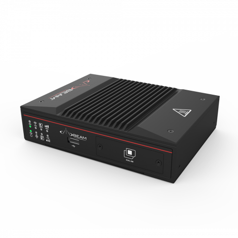
MG400 LTE Gateway (MG400)
Beam Communications undertakes warranty and out of warranty servicing across our extensive product range.
For further information on our servicing process, warranty items and conditions please click on the button below.
Frequently Asked Questions
Powering Up/Restarting
Both the MG400 and MG200 require 9-36V DC with minimum power rating of 24W.
The device does not have a physical on/off switch. Once connected to the power source the device will automatically switch on. Please allow 3 mins until the device is up and running normally before connecting to it.
If the device doesn’t switch on, please check following:
Check the pin connection on the terminal block connector. For the MG400, pin 1 is positive DC supply while pin 2 is ground. For the MG200, pin 1 is ground while pin 2 is positive DC supply.
If using an AC power supply it is recommended to use the supplied AC plug pack in the box.
When wiring it from an existing DC power source, voltage should be between 9-36V DC, with a minimum current of 2A at 12V.
If the supplies are at the correct levels and yet the device is unable to switch on, check the fuse on the DC power cable. Also check the DC cable connection to batteries.
Once power is connected, please allow 3 minutes for the device to completely boot up. During the boot up process, LEDs on the MG400 front panel will flash and then grey out. This is normal.
If the device switches off after a few minutes of operation. Please check following:
For both MG400 and MG200 if using the AC adapter, check AC power adapter if plugged in securely.
For DC power, check the fuse in DC power cable and the DC source outputs the correct voltage and current.
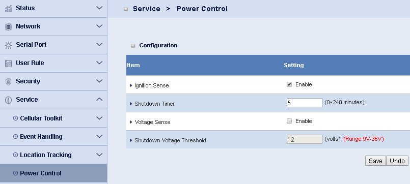
The MG400 unlike the MG200 has an Ignition Sense pin which allows it to switch-on and off with other electrical accessories in a vehicle.
When the Ignition Sense detects zero or low voltage, the MG400 will automatically switch off (per shutdown Timer setting in Power Control menu).
To disable / change the setting, in device Web GUI navigate to Service -> Power Control. See image below:
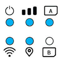
For the MG200 with GPS antenna connected, SIM A is selected, and LTE signal is high, see image below.
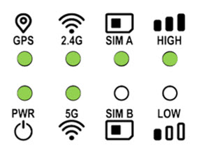
For the MG400 with GPS antenna connected, SIM A is selected, and LTE signal is high, see image below.
PIN/Security
For the MG200: 3FF, Micro SIM, 12 x 15 mm.
For the MG400: 2FF, Mini SIM, 25 x 15 mm.
The SIM card slot on MG400 is in device's front panel.
While the MG200, the SIM card slot is in the bottom panel.
Please refer to each product's Quick Start Guide for detailed instructions of how to insert the SIM cards.
SIM A and SIM B slots are the same, except by default setting the preferred SIM Card is SIM A. If both sim slots have sim cards in them, SIM A will be selected as default.
This setting can be changed via device Web GUI, Network -> Connection Setup -> Click Edit at WAN-1 -> Preferred SIM Card in 3G/4G WAN Type Configuration.
If one SIM card is inserted, the device will automatically detect the SIM card, no matter if it is in SIM A or SIM B slot.
SIM B can also be enabled as the fail-over to SIM A under the setting - Preferred SIM Card in 3G/4G WAN Type Configuration menu.
After power on, please allow 3 minutes for the device to boot up.
Either SIM A or SIM B LED will light up depending on which sim slot the sim card was inserted. For best practice, always use SIM A.
If none of the SIM A and SIM B LED is on, this means sim card is not detected.
Disconnect power, remove the sim card, make sure the sim contacts are clean, then insert it to the SIM slot following the correct orientation.
Refer to Quick Start Guide for detailed instructions of how to insert a SIM card.
By default SIM A is selected as preferred SIM card. SIM A LED is on. While SIM B is the backup sim card. SIM B LED will be off when SIM A is connected.
SIM B will be activated in following scenarios:
Only one SIM card is used and inserted to SIM B.
Both SIM A and SIM B slots have sim cards in them, but SIM B has been selected as the preferred SIM card.
Both SIM A and SIM B slots have sim cards in them, SIM A has been selected as the preferred SIM card, SIM B is enabled as Fallback, and there is no network connection on SIM A network.
In device Web GUI, navigate to Network -> Wi-Fi -> Wi-Fi Module One (or Two) -> Click Edit in 2.4G / 5G VAP List, change the SSID and Preshared Key settings.
Click Save, then click apply. Wait for a few seconds for the settings being activated.
There is a device label attached to the bottom of your device with the default Wi-Fi SSID and password.
If the label has become unreadable, the SSID and password can be read from device Web GUI: Network -> Wi-Fi -> Wi-Fi Module One (or Two) -> Click Edit in 2.4G / 5G VAP List, check the SSID and Preshared Key field.
If your smart phone or computer cannot connect to the MG200/MG400 because it can't see it's WiFi SSID, please follow the steps below:
Step 1: Enable the Wi-Fi function on your device (smart phone or computer), scan the Wi-Fi network. If using an MG400 and your device doesn’t support 5GHz Wi-Fi, you should still see the 2.4GHz Wi-Fi network created by MG400. The MG200 only supports 2.4G Wi-Fi.
Step 2: Select the MG200/MG400 Wi-Fi network, enter the Wi-Fi password.
If your device can not connect to the Wi-Fi network due to Wi-Fi channel interference, reboot your device. After the reboot, the device will select the best channel and keep using that channel.
Signal/Connectivity
Multiple factors may block cellular network connection.
Please check following:
- Make sure LTE antennas are securely tightened to the connector.
- Check APN setting. Make sure the correct APN is entered. You can enter the APN on page 5 on MG200 and page 6 on MG400. Or navigate to Network -> Connection Setup -> Click Edit at WAN-1 -> Enter the APN in Connection with SIM-A / SIM-B table.
- For a PIN locked SIM card, to unlock the SIM, please refer the Quick Start Guide.
- Also, check service provider for cellular network coverage and if there's any network issues on your service.
The 2.4G/5G LED indicates the working status of 2.4GHz/5GHz Wi-Fi module. Please refer to Quick Start Guide for the LED behavior and meanings.
Connect your PC to the device via Wi-Fi network or RJ45 cable. To access the Web GUI, on web browser of your PC, enter IP address 192.168.123.254.
To log in the device, enter the default user name ‘admin’, password ‘admin’.
For security reasons, it is recommended you change these login details at the 1st login.
Don't panic. The admin username and password can be reset, but this also resets the settings made in the modem.
First, you will need to reset the device back to factory default setting by pressing the reset button for 6 seconds.
Then connect your PC to the device via Wi-Fi network or a RJ45 cable.
Please note that the Wi-Fi SSID and password go back to factory default setting after the reset.
You may need to use the SSID and password printed on device label for Wi-Fi connection.
After connecting to the device, you can use the username ‘admin’ as administrator name and password to login.
Please change the login password in 2nd step of setup wizard, or navigate to administration -> System Operation -> Password & MMI -> Password.
The device has been programmed with Wi-Fi SSID and password before it leaves the factory.
The default SSID and password are printed on the device label.
In your first login to the device, when Setup Wizard page comes, it is recommended to change the default administrator password, Wi-Fi SSID and password.
Sure, you can. You can set up your home internet as the primary connection, and cellular as backup connection.
Before you connect the home internet to MG200/MG400, please configure the MG200/MG400.
In device Web GUI, navigate to Network -> WAN & Uplink -> Physical Interface -> Click Edit on WAN-1.
Select Ethernet as the Physical Interface, so that Ethernet is the primary WAN interface. Click Save.
Click Edit on WAN-2, select Failover WAN-1 at Operation Mode, then select 3G/4G at Physical Interface. Click Save to save the setting.
Now you can connect WAN/LAN1 port to your home internet with a RJ45 cable.
The integrated cellular module supports all the 3G and 4G bands in Australia.
Therefore, it supports all operator networks (Telstra, Optus, Vodafone, TPG) in Australia.
The LTE and Wi-Fi antennas that comes with the MG200/MG400 comes standard in the package and have been tested per CTIA test cases.
According to the test reports, the Total Isotropic Sensitivity (TIS) and Total Radiated Sensitivity (TRS) are far better than the specs recommended by Telstra.
Therefore, we recommend using the antennas for the applications where the indoor antenna is enough.
If external high gain antenna is required, it is suggested to use the antenna supplied by Beam Communications.
The Fast Ethernet port can transmit 10 and 100 Mbps. While the Gigabit Ethernet port can transmit 10, 100 and 1000 Mbps.
When a Fast Ethernet device connects with a Gigabit Ethernet device, the transmit speed will compromise to 100 Mbps.
If you are using a PC/server with the Gigabit Ethernet port, it is recommended to select an MG400, which has Gigabit Ethernet port so that you can maintain 1000 Mbps speed.
The upload speed is the speed from your device (smart phone or computer) to the network. The download speed is the speed from network to your device.
Normally the upload speed is much lower than download speed. This is because most Internet users have much more data to download then upload.
Then the network is designed and optimized for data download.
The integrated LTE module in MG400 and MG200 supports LTE Category 13, maximum download data rate is up to 391 Mbit/s.
2.4GHz and 5GHz are different operation radio frequencies on Wi-Fi. Some major differences:
- 2.4GHz popular standards: 802.11b/g/n. 5GHz popular standards: 802.11a/n/ac.
- 2.4GHz has better coverage than 5GHz.
- 2.4GHz has less RF channels than 5GHz. More interference and congestion happen in 2.4GHz.
- 2.4GHz normally has less bandwidth/speed than 5GHz.
While the ‘5G’ in ‘5G mobile network’ stands for 5 Generation. It doesn’t stands for a specific radio frequency.
Latency 802.11g/b devices devices force the Wi-Fi router to work at 802.11g/b mode which slow the 802.11n and 802.11ac devices.
It is suggested to isolated the 802.11g/b devices from 802.11ac, or update those devices to support 802.11n or 802.11ac.
While the ‘5G’ in ‘5G mobile network’ stands for 5 Generation.
Tracking
For location tracking applications connect the GPS antenna to the modem's GPS antenna port.
If location tracking is not required, then no need to connect GPS antenna. The GPS LED is to indicate the status of the GPS after the antenna is connected.
To use the tracking function follow the steps below:
Step 1: Stick a magnetic GPS antenna to the top of a vehicle or boat. It is recommended to use the GPS antenna supplied by BEAM Communications.
Step 2: When the device is powered off, connect the end of the GPS antenna cable to the GPS port of the device.
Step 3: Switch on the device. In device Web GUI, navigate to Service -> Location Tracking -> GNSS. Enable GNSS. Then configure the settings as per your requirement.
Manuals & Guides
Quick Start Guide MG400 LTE Gateway
Compliance
Frequently Asked Questions
Powering Up/Restarting
Both the MG400 and MG200 require 9-36V DC with minimum power rating of 24W.
The device does not have a physical on/off switch. Once connected to the power source the device will automatically switch on. Please allow 3 mins until the device is up and running normally before connecting to it.
If the device doesn’t switch on, please check following:
Check the pin connection on the terminal block connector. For the MG400, pin 1 is positive DC supply while pin 2 is ground. For the MG200, pin 1 is ground while pin 2 is positive DC supply.
If using an AC power supply it is recommended to use the supplied AC plug pack in the box.
When wiring it from an existing DC power source, voltage should be between 9-36V DC, with a minimum current of 2A at 12V.
If the supplies are at the correct levels and yet the device is unable to switch on, check the fuse on the DC power cable. Also check the DC cable connection to batteries.
Once power is connected, please allow 3 minutes for the device to completely boot up. During the boot up process, LEDs on the MG400 front panel will flash and then grey out. This is normal.
If the device switches off after a few minutes of operation. Please check following:
For both MG400 and MG200 if using the AC adapter, check AC power adapter if plugged in securely.
For DC power, check the fuse in DC power cable and the DC source outputs the correct voltage and current.
The MG400 unlike the MG200 has an Ignition Sense pin which allows it to switch-on and off with other electrical accessories in a vehicle.
When the Ignition Sense detects zero or low voltage, the MG400 will automatically switch off (per shutdown Timer setting in Power Control menu).
To disable / change the setting, in device Web GUI navigate to Service -> Power Control. See image below:

For the MG200 with GPS antenna connected, SIM A is selected, and LTE signal is high, see image below.

For the MG400 with GPS antenna connected, SIM A is selected, and LTE signal is high, see image below.

PIN/Security
For the MG200: 3FF, Micro SIM, 12 x 15 mm.
For the MG400: 2FF, Mini SIM, 25 x 15 mm.
The SIM card slot on MG400 is in device's front panel.
While the MG200, the SIM card slot is in the bottom panel.
Please refer to each product's Quick Start Guide for detailed instructions of how to insert the SIM cards.
SIM A and SIM B slots are the same, except by default setting the preferred SIM Card is SIM A. If both sim slots have sim cards in them, SIM A will be selected as default.
This setting can be changed via device Web GUI, Network -> Connection Setup -> Click Edit at WAN-1 -> Preferred SIM Card in 3G/4G WAN Type Configuration.
If one SIM card is inserted, the device will automatically detect the SIM card, no matter if it is in SIM A or SIM B slot.
SIM B can also be enabled as the fail-over to SIM A under the setting - Preferred SIM Card in 3G/4G WAN Type Configuration menu.
After power on, please allow 3 minutes for the device to boot up.
Either SIM A or SIM B LED will light up depending on which sim slot the sim card was inserted. For best practice, always use SIM A.
If none of the SIM A and SIM B LED is on, this means sim card is not detected.
Disconnect power, remove the sim card, make sure the sim contacts are clean, then insert it to the SIM slot following the correct orientation.
Refer to Quick Start Guide for detailed instructions of how to insert a SIM card.
By default SIM A is selected as preferred SIM card. SIM A LED is on. While SIM B is the backup sim card. SIM B LED will be off when SIM A is connected.
SIM B will be activated in following scenarios:
Only one SIM card is used and inserted to SIM B.
Both SIM A and SIM B slots have sim cards in them, but SIM B has been selected as the preferred SIM card.
Both SIM A and SIM B slots have sim cards in them, SIM A has been selected as the preferred SIM card, SIM B is enabled as Fallback, and there is no network connection on SIM A network.
In device Web GUI, navigate to Network -> Wi-Fi -> Wi-Fi Module One (or Two) -> Click Edit in 2.4G / 5G VAP List, change the SSID and Preshared Key settings.
Click Save, then click apply. Wait for a few seconds for the settings being activated.
There is a device label attached to the bottom of your device with the default Wi-Fi SSID and password.
If the label has become unreadable, the SSID and password can be read from device Web GUI: Network -> Wi-Fi -> Wi-Fi Module One (or Two) -> Click Edit in 2.4G / 5G VAP List, check the SSID and Preshared Key field.
If your smart phone or computer cannot connect to the MG200/MG400 because it can't see it's WiFi SSID, please follow the steps below:
Step 1: Enable the Wi-Fi function on your device (smart phone or computer), scan the Wi-Fi network. If using an MG400 and your device doesn’t support 5GHz Wi-Fi, you should still see the 2.4GHz Wi-Fi network created by MG400. The MG200 only supports 2.4G Wi-Fi.
Step 2: Select the MG200/MG400 Wi-Fi network, enter the Wi-Fi password.
If your device can not connect to the Wi-Fi network due to Wi-Fi channel interference, reboot your device. After the reboot, the device will select the best channel and keep using that channel.
Signal/Connectivity
Multiple factors may block cellular network connection.
Please check following:
- Make sure LTE antennas are securely tightened to the connector.
- Check APN setting. Make sure the correct APN is entered. You can enter the APN on page 5 on MG200 and page 6 on MG400. Or navigate to Network -> Connection Setup -> Click Edit at WAN-1 -> Enter the APN in Connection with SIM-A / SIM-B table.
- For a PIN locked SIM card, to unlock the SIM, please refer the Quick Start Guide.
- Also, check service provider for cellular network coverage and if there's any network issues on your service.
The 2.4G/5G LED indicates the working status of 2.4GHz/5GHz Wi-Fi module. Please refer to Quick Start Guide for the LED behavior and meanings.
Connect your PC to the device via Wi-Fi network or RJ45 cable. To access the Web GUI, on web browser of your PC, enter IP address 192.168.123.254.
To log in the device, enter the default user name ‘admin’, password ‘admin’.
For security reasons, it is recommended you change these login details at the 1st login.
Don't panic. The admin username and password can be reset, but this also resets the settings made in the modem.
First, you will need to reset the device back to factory default setting by pressing the reset button for 6 seconds.
Then connect your PC to the device via Wi-Fi network or a RJ45 cable.
Please note that the Wi-Fi SSID and password go back to factory default setting after the reset.
You may need to use the SSID and password printed on device label for Wi-Fi connection.
After connecting to the device, you can use the username ‘admin’ as administrator name and password to login.
Please change the login password in 2nd step of setup wizard, or navigate to administration -> System Operation -> Password & MMI -> Password.
The device has been programmed with Wi-Fi SSID and password before it leaves the factory.
The default SSID and password are printed on the device label.
In your first login to the device, when Setup Wizard page comes, it is recommended to change the default administrator password, Wi-Fi SSID and password.
Sure, you can. You can set up your home internet as the primary connection, and cellular as backup connection.
Before you connect the home internet to MG200/MG400, please configure the MG200/MG400.
In device Web GUI, navigate to Network -> WAN & Uplink -> Physical Interface -> Click Edit on WAN-1.
Select Ethernet as the Physical Interface, so that Ethernet is the primary WAN interface. Click Save.
Click Edit on WAN-2, select Failover WAN-1 at Operation Mode, then select 3G/4G at Physical Interface. Click Save to save the setting.
Now you can connect WAN/LAN1 port to your home internet with a RJ45 cable.
The integrated cellular module supports all the 3G and 4G bands in Australia.
Therefore, it supports all operator networks (Telstra, Optus, Vodafone, TPG) in Australia.
The LTE and Wi-Fi antennas that comes with the MG200/MG400 comes standard in the package and have been tested per CTIA test cases.
According to the test reports, the Total Isotropic Sensitivity (TIS) and Total Radiated Sensitivity (TRS) are far better than the specs recommended by Telstra.
Therefore, we recommend using the antennas for the applications where the indoor antenna is enough.
If external high gain antenna is required, it is suggested to use the antenna supplied by Beam Communications.
The Fast Ethernet port can transmit 10 and 100 Mbps. While the Gigabit Ethernet port can transmit 10, 100 and 1000 Mbps.
When a Fast Ethernet device connects with a Gigabit Ethernet device, the transmit speed will compromise to 100 Mbps.
If you are using a PC/server with the Gigabit Ethernet port, it is recommended to select an MG400, which has Gigabit Ethernet port so that you can maintain 1000 Mbps speed.
The upload speed is the speed from your device (smart phone or computer) to the network. The download speed is the speed from network to your device.
Normally the upload speed is much lower than download speed. This is because most Internet users have much more data to download then upload.
Then the network is designed and optimized for data download.
The integrated LTE module in MG400 and MG200 supports LTE Category 13, maximum download data rate is up to 391 Mbit/s.
2.4GHz and 5GHz are different operation radio frequencies on Wi-Fi. Some major differences:
- 2.4GHz popular standards: 802.11b/g/n. 5GHz popular standards: 802.11a/n/ac.
- 2.4GHz has better coverage than 5GHz.
- 2.4GHz has less RF channels than 5GHz. More interference and congestion happen in 2.4GHz.
- 2.4GHz normally has less bandwidth/speed than 5GHz.
While the ‘5G’ in ‘5G mobile network’ stands for 5 Generation. It doesn’t stands for a specific radio frequency.
Latency 802.11g/b devices devices force the Wi-Fi router to work at 802.11g/b mode which slow the 802.11n and 802.11ac devices.
It is suggested to isolated the 802.11g/b devices from 802.11ac, or update those devices to support 802.11n or 802.11ac.
While the ‘5G’ in ‘5G mobile network’ stands for 5 Generation.
Tracking
For location tracking applications connect the GPS antenna to the modem's GPS antenna port.
If location tracking is not required, then no need to connect GPS antenna. The GPS LED is to indicate the status of the GPS after the antenna is connected.
To use the tracking function follow the steps below:
Step 1: Stick a magnetic GPS antenna to the top of a vehicle or boat. It is recommended to use the GPS antenna supplied by BEAM Communications.
Step 2: When the device is powered off, connect the end of the GPS antenna cable to the GPS port of the device.
Step 3: Switch on the device. In device Web GUI, navigate to Service -> Location Tracking -> GNSS. Enable GNSS. Then configure the settings as per your requirement.


